

The Implant NAVI acquires data of embedded depth, displacement, and inclination of the piles being installed in real time. It is an integrated system that realises high quality pile installation control, automatic creation of various as-built documents, and creation of 3D drawings.
Pile Installation Quality Control System through automatic creation of various as-built documents, and visualisation of the structure with 3D drawings
Features of the Implant NAVI
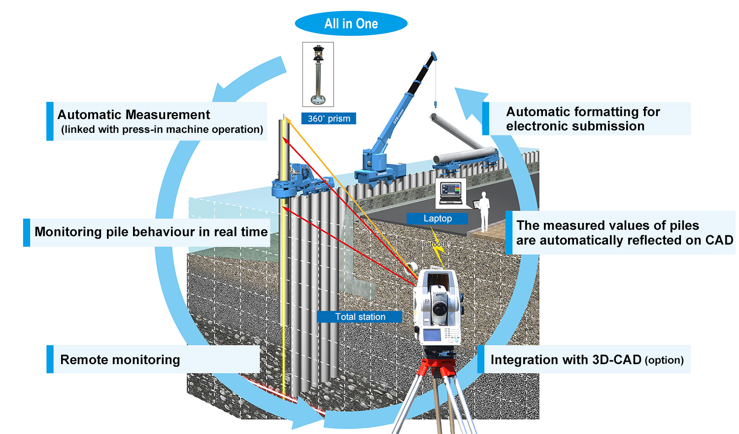
Automatic Measurement (linked with press-in machine operation)
In conjunction with operations of the press-in machine SILENT PILER™ and GYRO PILER (F series) such as Chuck Open / Close, Rotation, Up/Down, it can automatically provide ideal measurements. No special qualification is required for measurement.
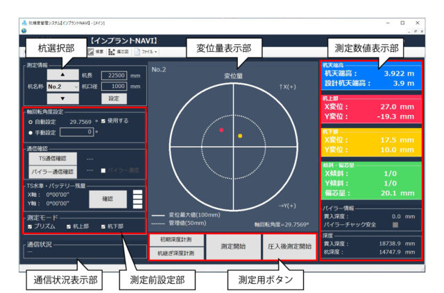
Monitoring pile behaviour in real time
Pile behaviour (penetration depth, displacement, inclination) can be monitored accurately in real time on a PC connected via Bluetooth™ during construction.
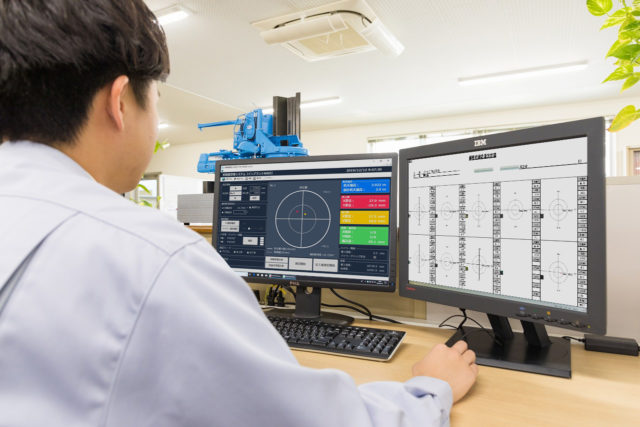
Remote monitoring
You can check the data in real time from distant places such as offices. (Viewable on PC, tablet and smartphone)
Integration with 3D-CAD (option)
It can automatically create 3D drawings from pile diameter, coordinate values, pile length, etc. Those 3D drawings (CIM * data) can be utilized for later work processes and maintenance work.
*CIM = Construction Information Modeling/Management (a chart created with any parameters by using 3D drawings of the structure)
The measured values of piles are automatically reflected on CAD
Measured values of the acquired piles are automatically reflected on CAD drawing. It is exported in DWG format, so the data is highly compatible.
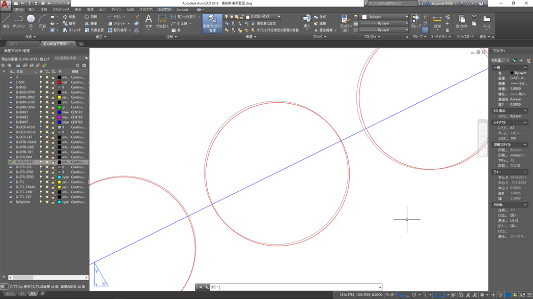
Black: Planed alignment, Red: Measured data
Automatic formatting for electronic submission
The measurement data is sent to the PC in real time, and then those data can be printed in a format for electronic submission.
・ Measurement result summary table
・ Measurement result list
・ As-built chart
・Pile deviation measurement diagram
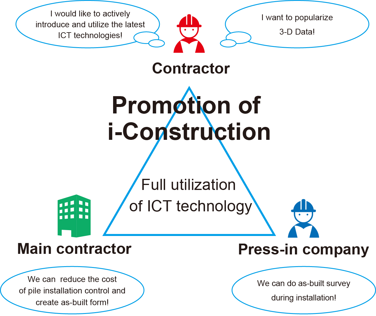
Advantages of the introduction of the Implant NAVI™ system
The Implant NAVI not only realises highly accurate pile installation management by checking the displacement and inclination of the piles while they are being installed but also reduces costs by creating as-built reports integrally in an electronic delivery format. Furthermore, construction status can be easily checked by the 3D visualisation of the constructed structures.
Measurement Method
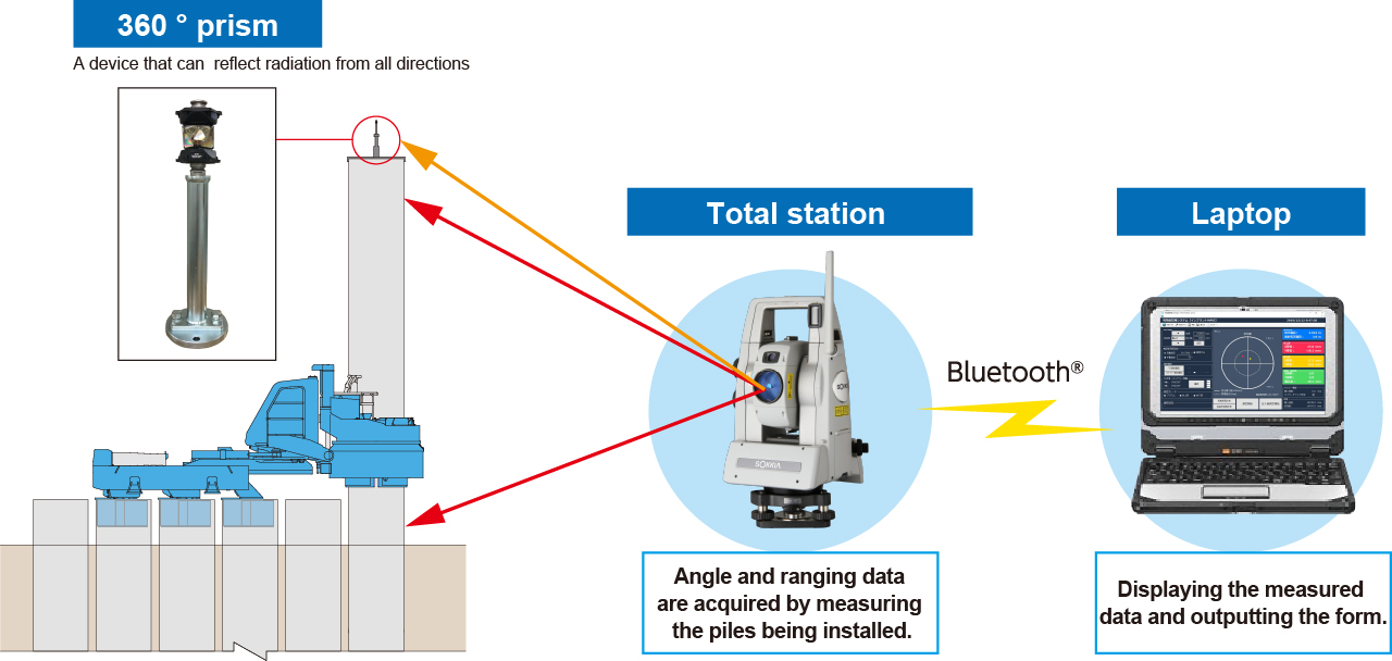
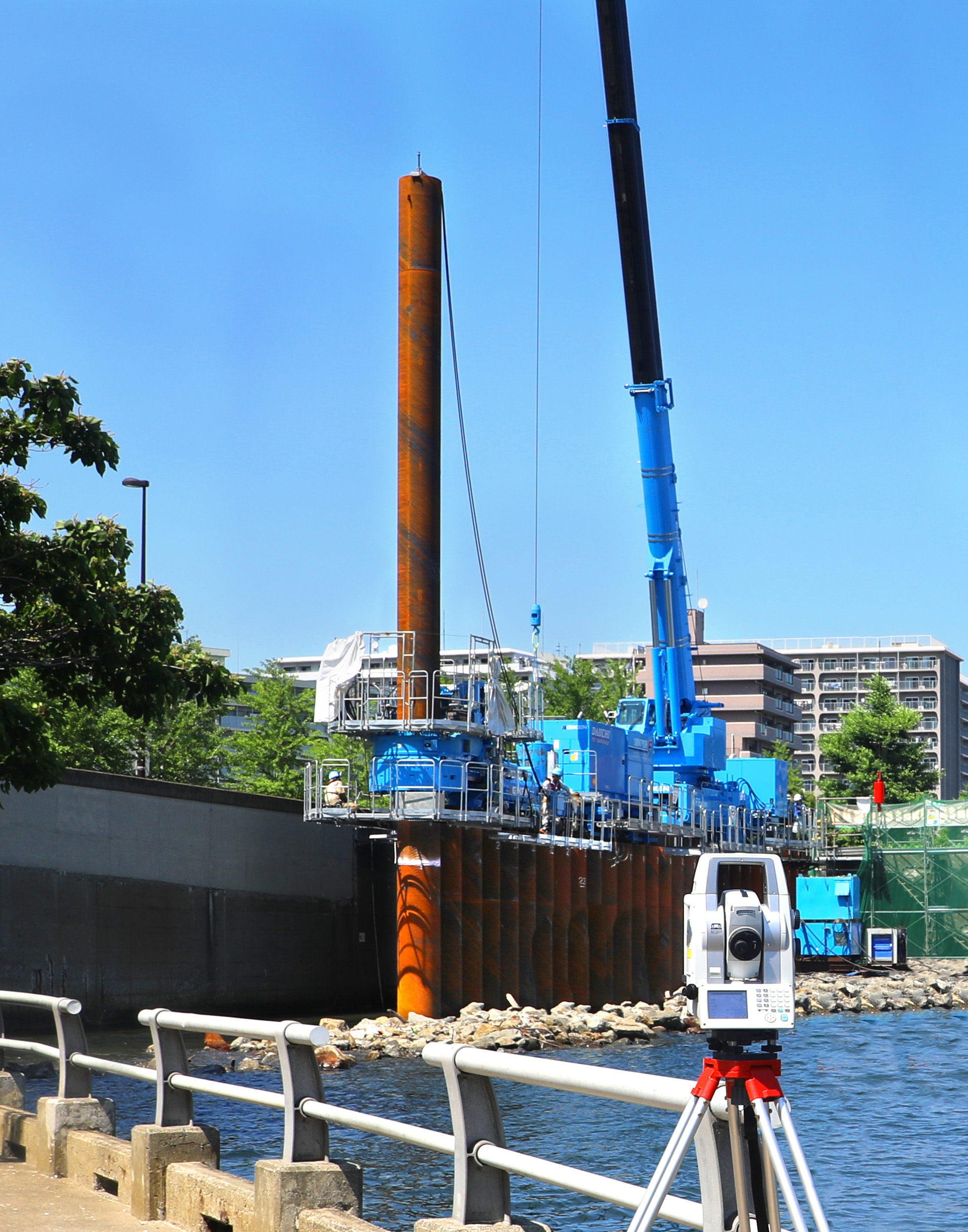
Total station is used for prism measurement and non-prism measurement.
360 ° prism is installed on the pile head and non-prism measurement is conducted at 2 points at each of the upper and lower parts of the pile.
Embedded depth is measured by automatically tracking the 360 ° prism at regular intervals.
Coordinate data is acquired by automatically measuring 4 points of the stopped pile when the chuck is opened and closed, by linking displacement and inclination of the pile with the press-in machine operations.
■Automatic generation of as-built reports and remote monitoring
The measurement data for each pile is stored on a laptop PC, and the actual measurements are automatically plotted on the planning lines of the construction drawings (2DCAD).
In addition, the data of completed piles can be used to output an as-built report in the format for electronic delivery.
Real-time data can be checked remotely from an offsite office with an internet connection.
Measurement Work Flow
Advance preparation
・Setting of pile diameter, pile length, and designed coordinates to PC for measurement
・Checking reference point coordinates
・Preparation for checking the height of the swivel attachment to be used (number of ports and drawings), and wire (about 2m)
Preparation for measurement
・Installation of total station (visual confirmation)
・Confirmation of prism installation, reference point, station point
・Installation of PC and communication verification, installation of Piler communication Power Unit and communication verification
Measurement
・Registration of measurement points, ensuring visibility
・Prism measurement: Auto tracking
・Non-prism Measurement: Automatic measurement in conjunction with press-in machine operation
Measurement results
・Measurement result list
・Deviation measurement diagram
・Time-varying amount diagram and depth-varying diagram
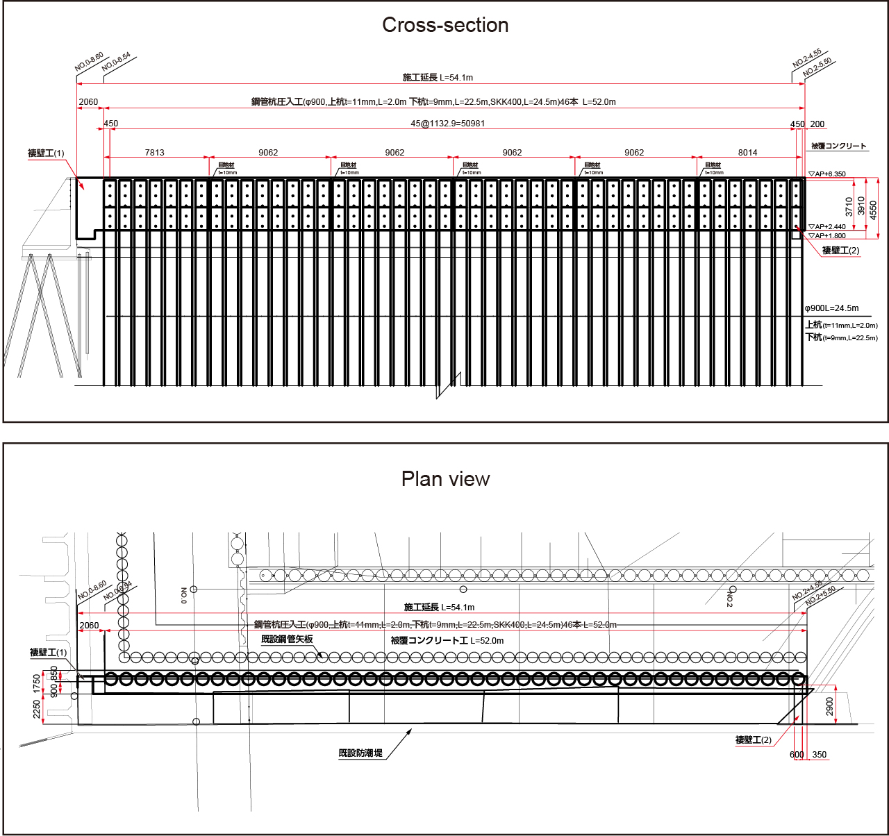
Project Achievement
| Project name | Sumida River (downstream of Aioi Bridge) Left Tide Wall Seismic Reinforcement Work (Phase2) and Terrace Work (Phase 3) |
| Type of work | Gyropress Method™ |
| Pile type | Tubular Pile |
| No. of measured piles | 46 piles |
| Duration *Tubular pile installations – as-built measurement after soil improvement | June 11 to November 21, 2019 |
Click to zoom-in
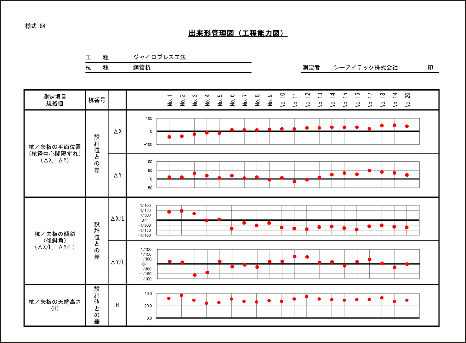
As-built chart(Process capability chart)
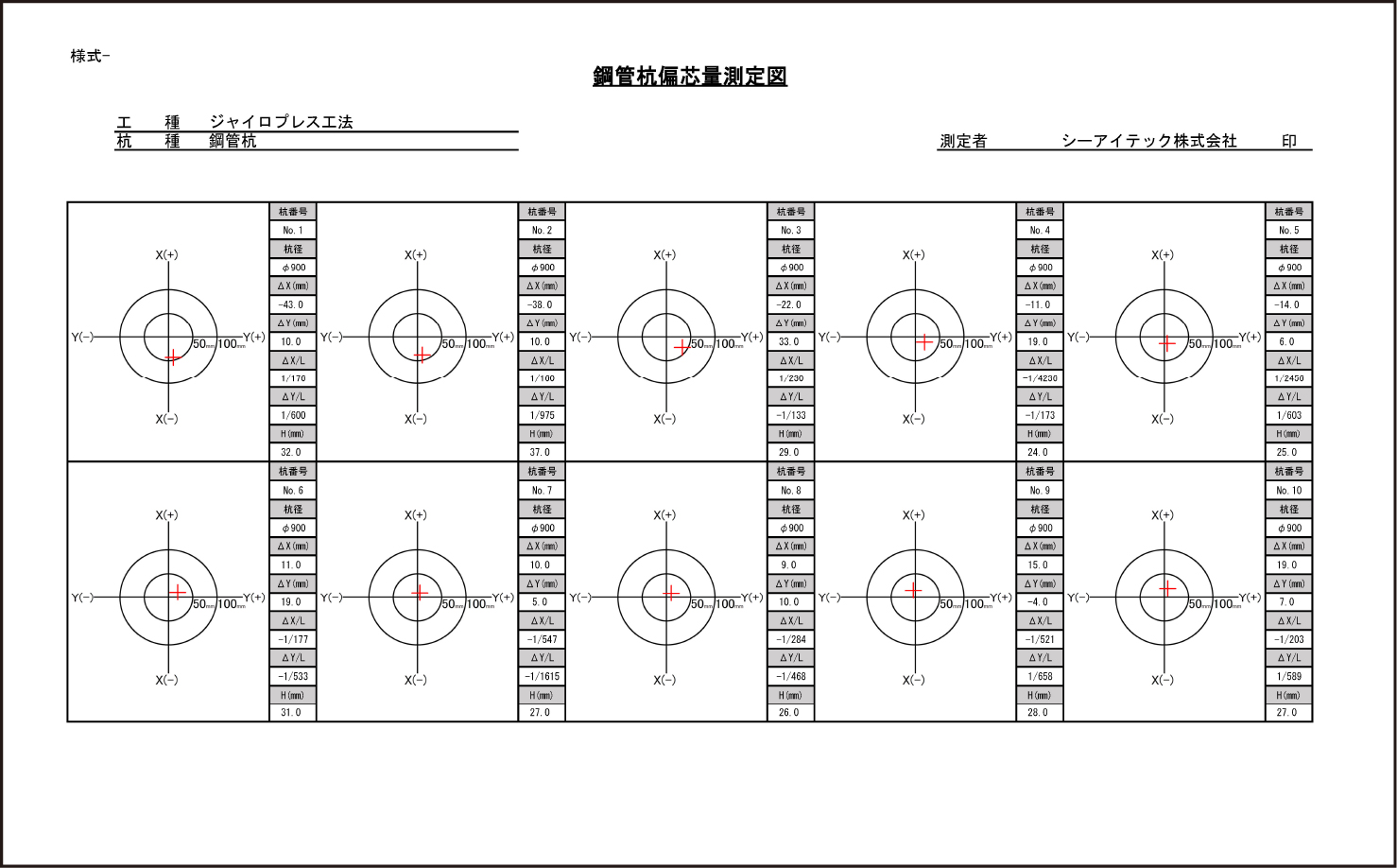
Deviation measurement diagram of Tubular pile
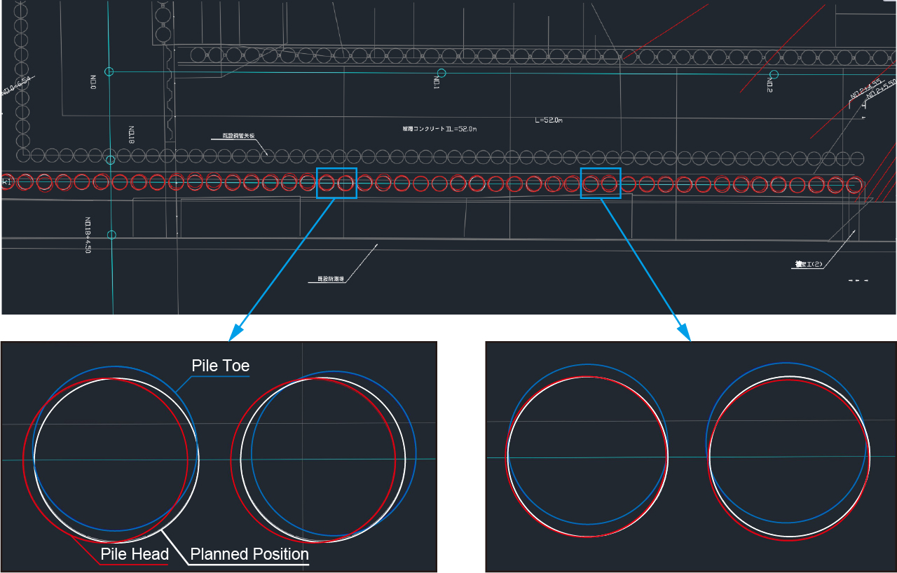
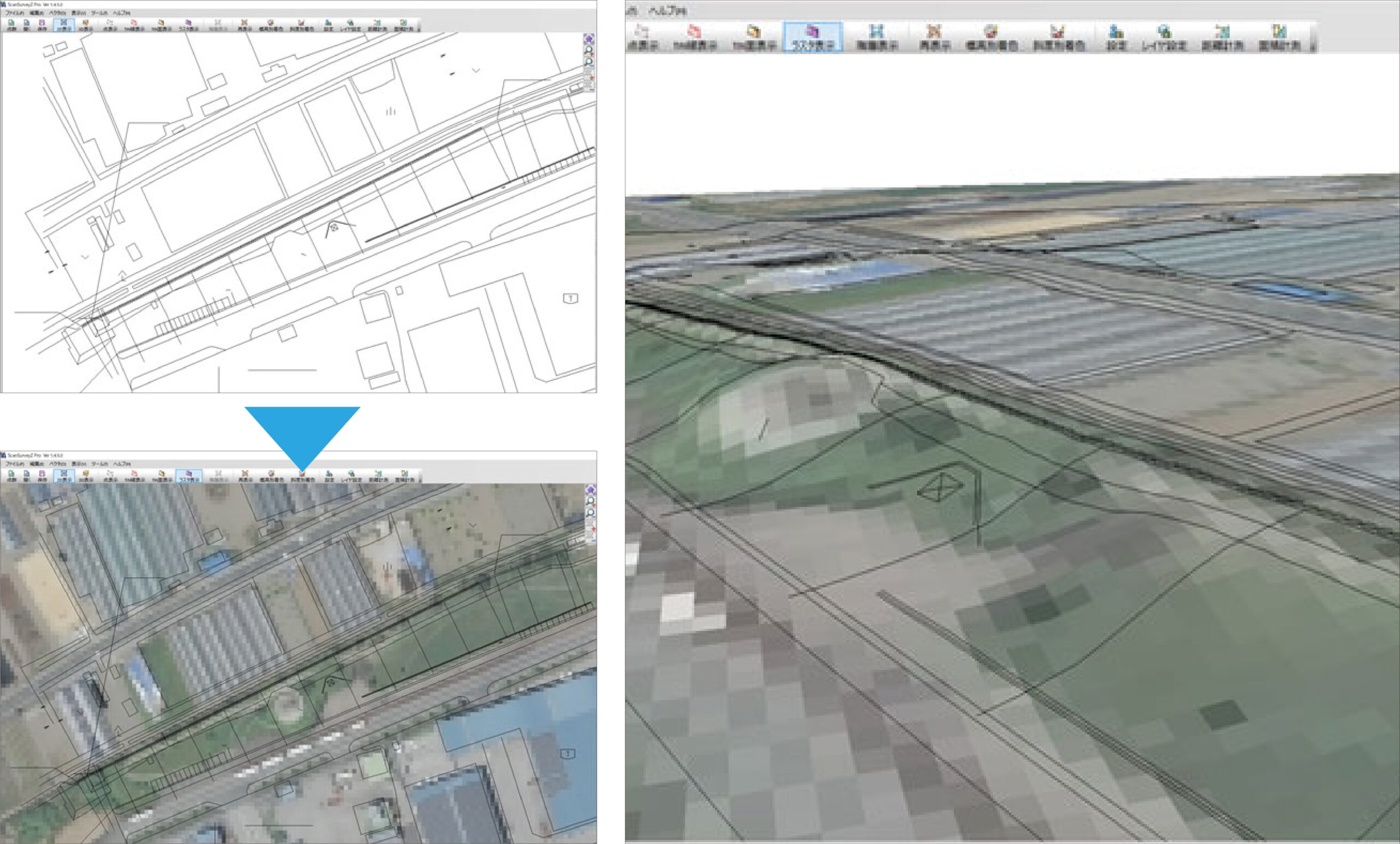
Reflecting the measured values on 2DCAD
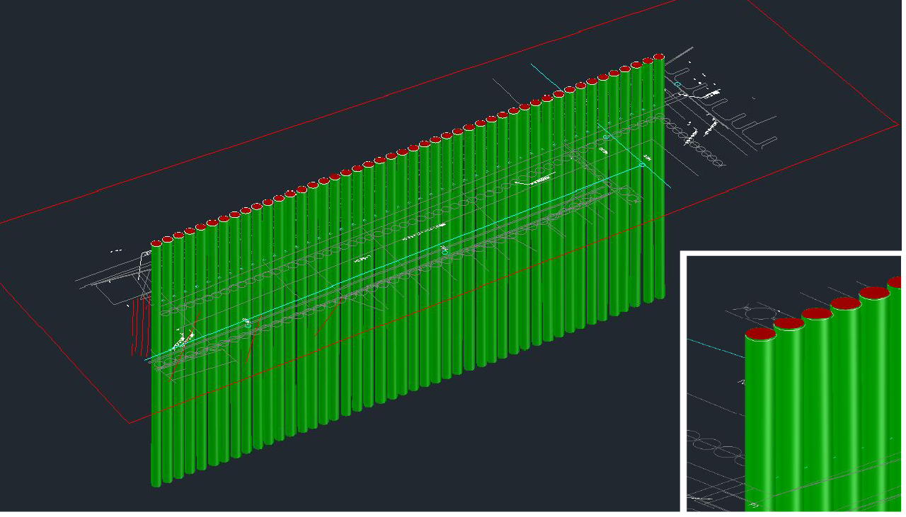
Outputting as 3D drawing data
Integrated function with 3D-CAD (optional)
It can automatically create 3D drawings from pile diameter, coordinate values, pile length, etc. By making structures "visible" using as-built 3D drawings, agreement formation can be accelerated and advanced among the people involved.
In addition, we can solve problems beforehand by examining later processes and maintenance-level processes in advance.
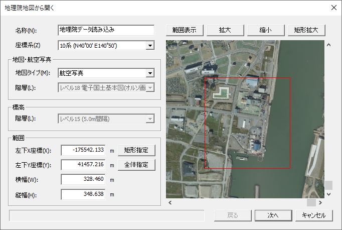
Geospatial Information Authority of Japan website
Electronic Land Data published by the Geospatial Information Authority of Japan can be used. The data can be freely selected according to the range of the construction site.
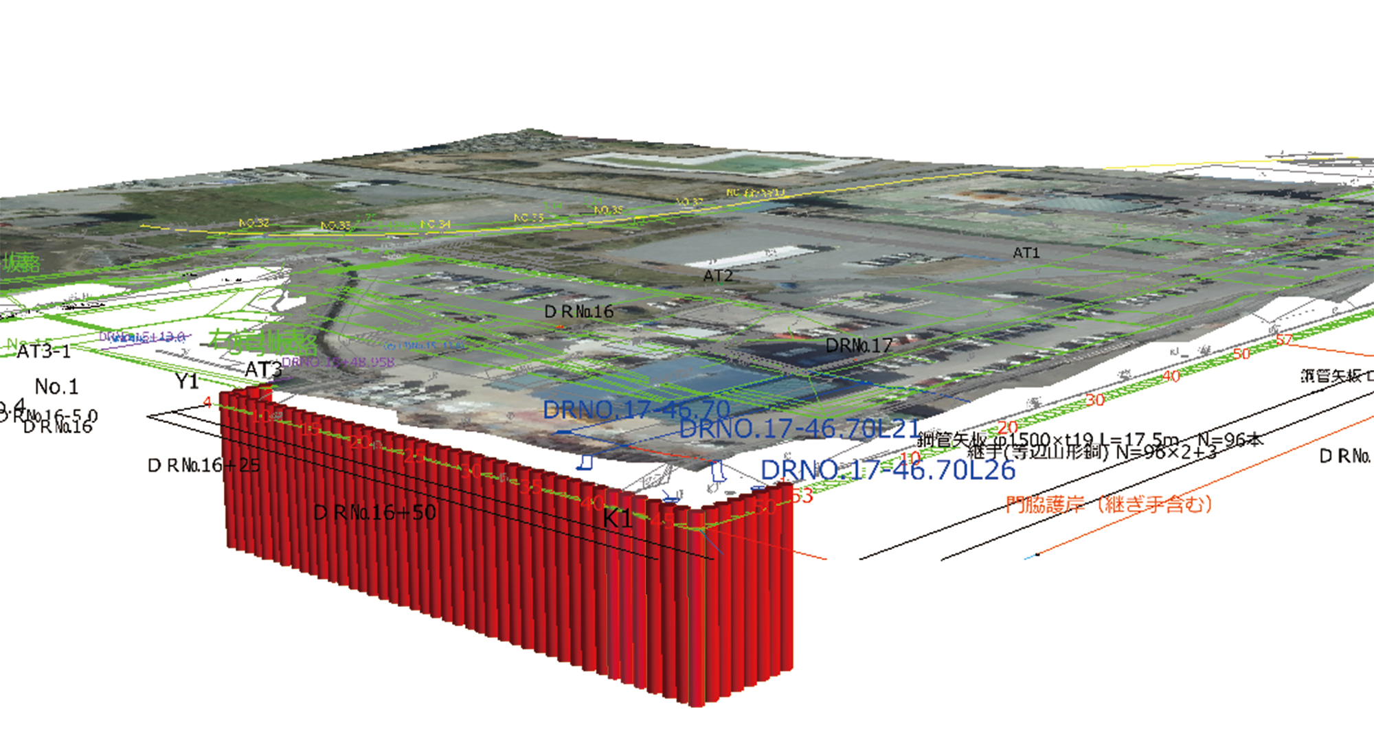
Data shots with drones are also available
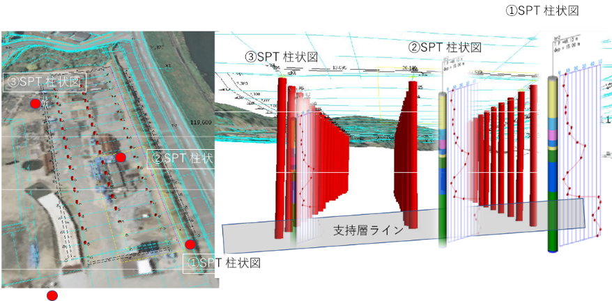
You can link 3D drawings with on-site data. Data can be checked in 2D or 3D and displayed in an easy-to-understand manner.
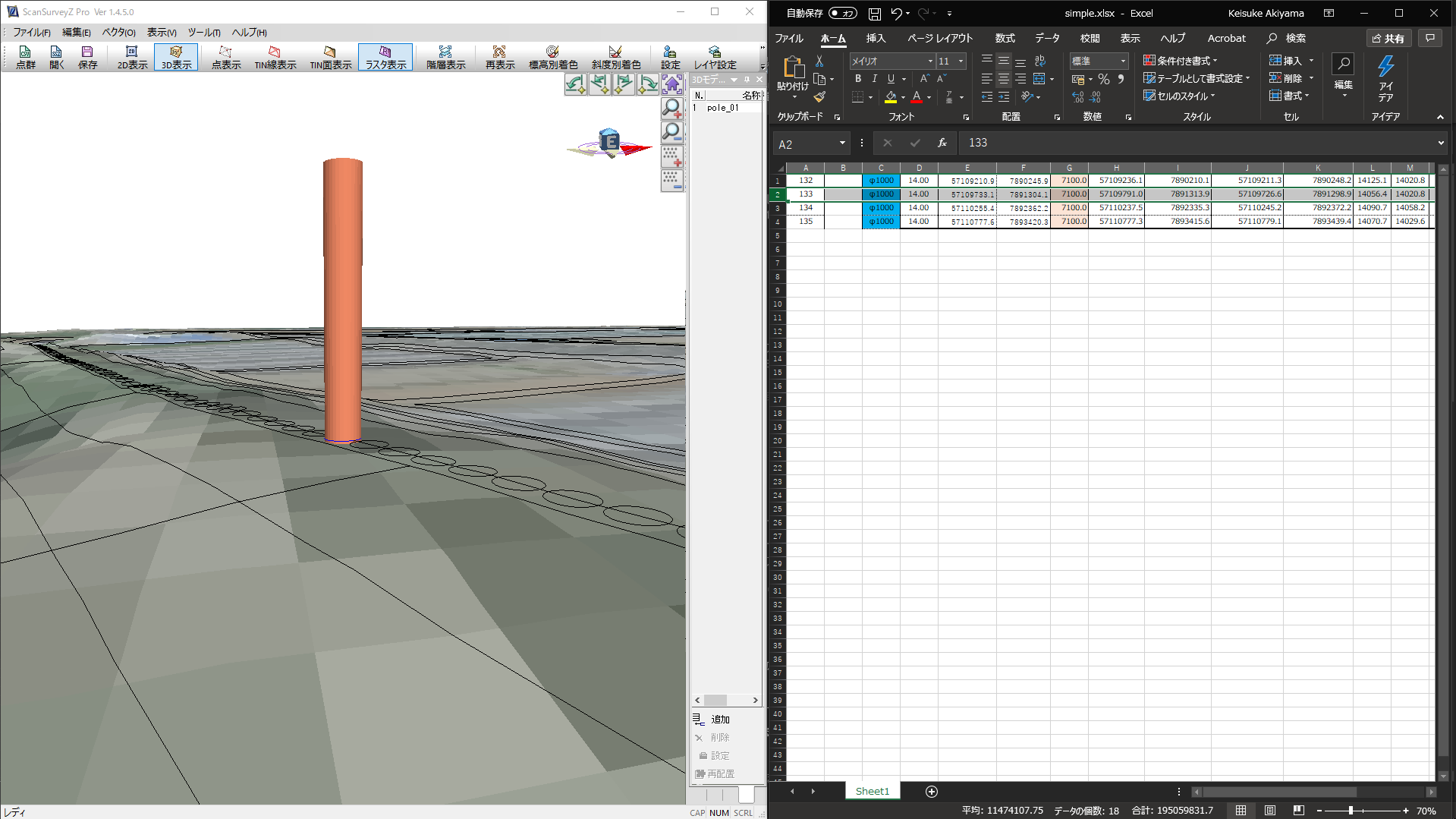
Integrated with EXCEL Data
You can integrate a 3D drawing with Excel to view and compare data. Click on a pile in the 3D data to see the corresponding information in the Excel sheet. Click on a cell in the Excel sheet to zoom in on the corresponding pile and highlight it.
Optional system for Implant NAVI™
Implant NAVI offers the following six options. Multiple combinations of the options are possible. Please contact us for further information as some construction cases may require consideration.
Small-diameter Pile Installation Quality Control System
This option provides accuracy control in installations of small-diameter steel tubular piles in a watertight method between steel tubular piles that require a high degree of accuracy in the installations. It is possible to accurately manage the installation of small-diameter steel tubular piles in line with the already installed tubular piles using this system.
Pile Closure Assistant System
Closure simulation is performed with this option using a 3D model created from pile installation data. It can be applied to circular and rectangular closures made of tubular sheet piles and tubular piles. The 3D drawing checks distance and inclination between the pile and closure point, allowing for advanced feasibility determination and countermeasures.
Pile-jointing Quality Control System
This option enables welding accuracy control in piling installations where tubular piles are welded together. It ensures that the inclination of the pile to be spliced matches the inclination data of the underground pile to avoid welding in a crooked condition.
Measurement System for Hat sheet piles
The displacement, inclination, and coordinate positions of a steel sheet pile being pressed-in is monitored in real-time using prisms attached above and below the joints.
3D Modelling System
Based on data from completed piles installed via the Implant NAVI and Press-in Monitoring System, a 3D model is created that can be delivered as CIM data. In addition, by installing the “Implant NAVI Viewer”, the 3D model data can be checked and shared with the contractor.
Small-networked Inclinometer System
The Implant NAVI estimates and quantifies the penetration angle of tubular piles and tubular sheet piles underground using above-ground measurement data to ensure installation accuracy. With this option, the position of the pile toe can be measured and compared with the measurement data from Implant NAVI by attaching a “small-networked inclinometer” to the pile material.